CWDM Transceivers: Distance and Power budget
Introduction
The CWDM (Coarse Wavelength Division Multiplexing) technology allows users to Multiplex/Demultiplex 18 different wavelengths over a single pair of optical fiber.
In theory, this technology allows link up to 160km without signal amplification. Basically, the distance is calculated out of many factors as per explained in this article.
Skylane Optics has a wide portfolio of CWDM transceivers from Fast Ethernet to 25x Gigabit Ethernet. To make it simpler, we have categorized the CWDM channels as per below tab from The ITU-T G.694.2.
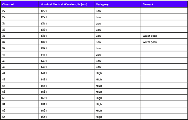
- Channels from 27 (1271nm) to 45 (1451nm) are considered as “lower channels” under Skylane Optics®
- Channels from 47 (1471nm) to 61 (1611nm) are considered as “upper channels” under Skylane Optics®
- Channels 35 (1351nm) and 37 (1371nm) are classified under “Water peak” due to the very high attenuation on traditional fibers. On low water peak optical fibers, channels 35 and 37 can be used without any problem.
How to calculate the distance of your CWDM transceiver
Several factors are used to calculate the distance you can reach:
Power budget: refers to the amount of loss a data link can tolerate while maintaining proper operation. In other words, it defines the amount of optical power available for successful transmitting signal over optical fiber. Power budget is the difference between the minimum (worst case) transmitter output power and the Receiver sensitivity.
Link margin: also called power budget margin generally includes aging of the fiber, aging of the transmitter and receiver components, additional devices, incidental twisting and bending of the fiber, additional splices, etc. The margin is needed to compensate for link degradation, which is within the range of 3 to 10dB.
MUX/DEMUX Pair Insertion loss: is the average loss of the signal when passing through a Multiplexer and then through a demultiplexer before reaching the other side of the link.
Connector Insertion loss: Is the loss of a mated pair of connectors. The loss will be different for every connector. For instances, multimode connectors will have losses of 0.2-0.5 dB typically while single-mode connectors will have losses of 0.1-0.2 dB.
Dispersion penalty: is the increment in the received power to eliminate the effect of some undesirable distortion in optical fiber. This value is given by the manufacturer
Fiber loss: fiber loss impacts greatly on overall system performance, which is expressed by dB per kilometer. The total fiber loss is calculated based on the distance × the loss factor (provided by manufacturer).
Based on All these factors, we will calculate the distance for the Skylane P/N SPC47070100D.
Information from Manufacturer:
- Maximum distance 70km without any loss of signal
- Minimum Tx Power: 0dBm
- Maximum Rx Sensitivity: -23dBm
- Power Budget: 23dB
- Dispersion Penalty: 5dB
Average Data:
- MUX/DEMUX Pair Insertion Loss: 5dB
- Connector Insertion Loss: 1dB
- Link Margin: 1-3dB
- Available for Fiber Attenuation: 12dB
- Fiber Attenuation @1550nm: 25dB/km
- Calculated Fiber Length: ~50km
Meaning that, based on a 70km part, and considering all losses over the signal, you can only reach about 50km.
For low channels around the 1310nm, the fiber attenuation is even bigger (0,4dB/km) and you can only reach 35 to 40km.

Distance VS Power Budget
Based on the above information, we can define for the upper channel (1471nm to 1611nm) a typical distance (Best case) per power budget and summarize them in a tab.

Source:
http://www.fiber-optic-transceiver-module.com/fiber-link-power-budget-calculation.html
Boost your networks with intelligent SFP+ transceivers, from 1G to 10G!

Powering AI and ML with Skylane Optics’ High Speed DACs

The importance of effective data center cabling management!
