Clock Data Recovery (CDR)

Many digital high-speed data streams, such as Ethernet, are transmitted without any specific clock information. Thus, the receiving end has to generate an incoming clock based on the received data. In practice, a phase-locked loop (PLL) aligns to the incoming data transitions and a proper clock signal can be extracted. The retrieved clock is also used to re-time the incoming data. This process is called Clock and Data Recovery (CDR).
The data stream must be coded in such a way that sufficient data transitions are present in the stream (i.e. to reduce the number of consecutive identical data symbols). A common coding scheme is 64B/66B encoding.
The main goal when transmitting an optical/electrical signal from one point to the other is to conserve the signal integrity to avoid any loss of data. A key feature is the ability to transfer timing information from source point to destination point. This timing feature is called Clock Data Recovery.
What is Clock Data Recovery?
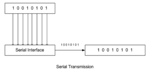
The Optical and electrical transceiver are using what we call the Serial Data Communication. In this kind of communication, the data bits are transmitted sequentially one by one.
Most transceivers today on the market do not have any dedicated clock input, hence functions such as clock recovery and data re-timing is performed outside the transceiver (i.e. on the host board). The receiver side needs then to recover the clock to sample the data coming on the serial lines.
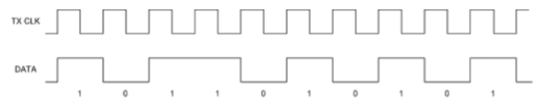
In order to accomplish that, the receive side needs a clock of approximately the same frequency as the incoming data. A recovered clock will be generated by phase aligning the reference clock to the transition on the incoming data signal. This is called Clock Recovery
The re-timing of incoming data signals using the recovered clock is called Data Recovery. Together, this is called Clock Data Recovery, or CDR.
In other words, the role of the CDR is to recover timing information from an incoming signal where there is no accompanying clock signal and to re-time the received data.
How does CDR work?
- Frequency detection
It locks on a frequency that is retrieved from incoming data stream. To do so, it detects the data transitions and locks an VCO (Voltage Controlled Oscillator) to that frequency. This frequency is then used when generating the transmitted data bit stream.
To make it short, the Rx frequency (destination clock) must be the same as the Tx frequency (Source clock).
To ease the frequency detection on the RX side, the data source will send a specific sequence of bits, called training sequence, before transmitting the real data stream. The training sequence is very dense, allowing the receiver to easily lock the frequency by checking the consecutive data waves on the wire before start of valid data.
2. Phase Alignment
It matches the phase of the clock, already recovered in frequency detection, with the incoming data bit stream. It will continuously adjust the clock based on variation in incoming data stream.
Below are the Skylane transceivers with integrated CDR:
- SPP85P300H0C
- SPP130100H0C
- SPP130020H0C
- SPP130400H0C
- SPP150400H0C
- SPP150800H0C
- SPCxx0400H0C
- SPCxx0700H0C
- XFP130100H0C
- XFP130200H0D
- XFP150400H0D
- XFP150800H0D
Source: protocol-debug.com
Boost your networks with intelligent SFP+ transceivers, from 1G to 10G!

Powering AI and ML with Skylane Optics’ High Speed DACs

The importance of effective data center cabling management!
